Every construction activity or building started life as a stack of paper (or, today, a set of PDF files) covered in lines, numbers, and symbols. Those documents are construction drawings, and without them, nothing gets built correctly.
Between architectural sheets, structural layouts, MEP overlays, and a dozen abbreviations nobody explains, it’s easy to see why drawings cause more confusion — and more expensive mistakes — than almost anything else on a building site.
At VIVEROCK, we produce and coordinate construction drawings on every project we design and build, from concept sketches to the final as-built record. This guide pulls that day-to-day experience into one resource: the most complete explanation of construction drawings you’ll find anywhere, covering 45+ drawing types, symbols, scales, drawing sets, software, and a step-by-step method for reading any drawing with confidence.
Quick Answer: Construction drawings are precise, scaled technical documents — prepared by architects, engineers, and designers — that communicate exactly what to build, where, out of what materials, and to what standard. They exist in dozens of specialized types across architectural, structural, civil, MEP, and fabrication disciplines, and progress through defined stages from concept to as-built record.
What Are Construction Drawings?
Construction drawings — also called technical drawings, working drawings, or construction documents — are the scaled, dimensioned instructions that turn a design idea into a buildable structure. They form part of the official contract documentation between the project owner and contractor, and they are what every trade on site ultimately builds from.
“Blueprint” is the term most people still reach for, but it’s technically outdated — it refers to a 19th-century cyanotype printing process that produced white lines on blue paper. That process disappeared generations ago; today’s correct term is construction drawing or technical drawing.
Construction drawings are usually accompanied by a specifications document, which spells out the exact materials, workmanship standards, and testing requirements the drawings alone can’t capture. Together, drawings and specifications form the technical backbone of the construction contract.
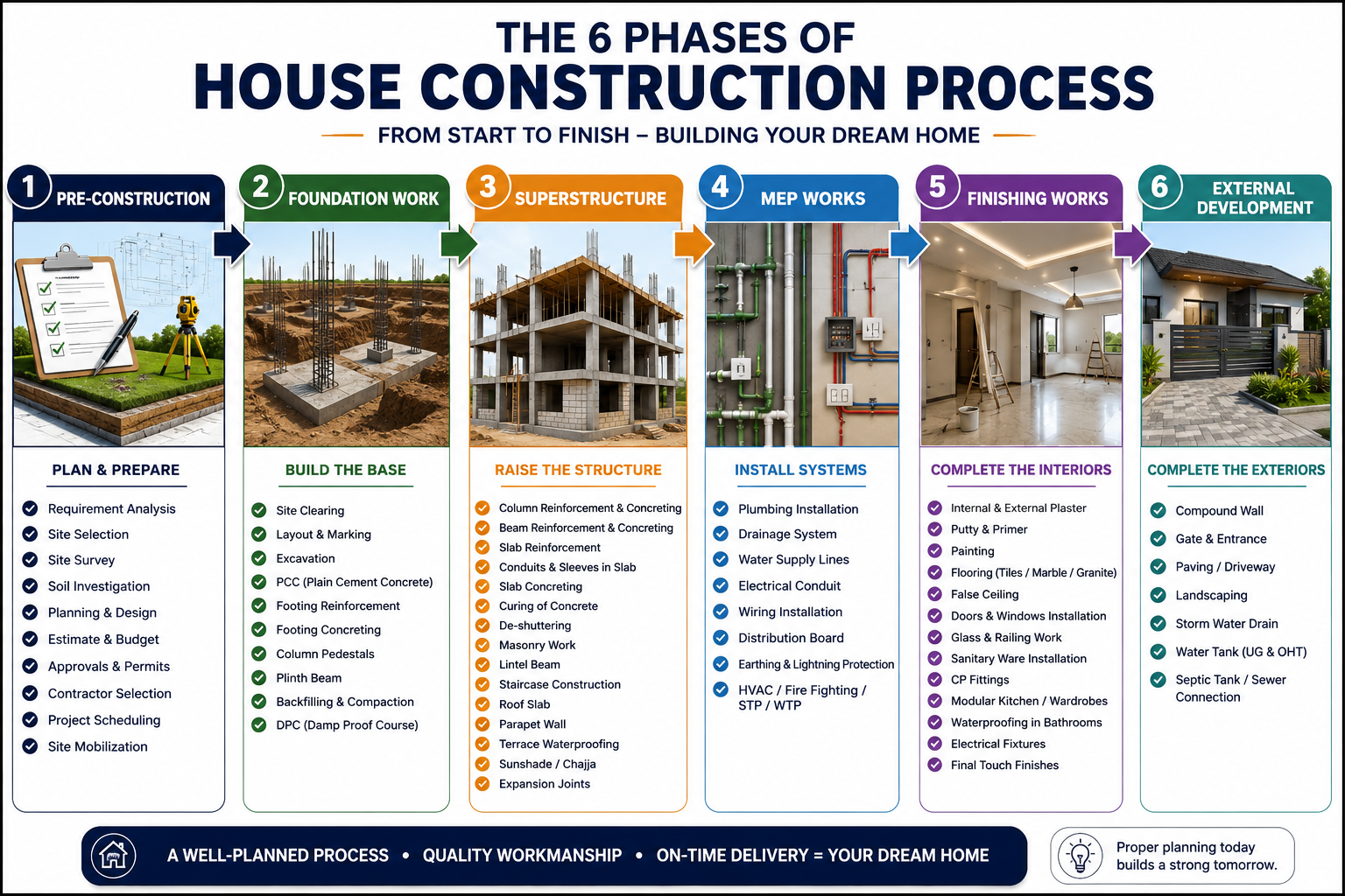
Read: Six phases of house construction in Kenya
Who Prepares Construction Drawings?
| Role | Drawings Produced |
|---|---|
| Architects | Floor plans, elevations, sections, schedules |
| Structural Engineers | Foundation, framing, and reinforcement drawings |
| MEP Engineers | Mechanical, electrical, plumbing, and fire protection drawings |
| Civil Engineers | Site, grading, drainage, and road drawings |
| Interior Designers | Furniture, finishes, and reflected ceiling plans |
| Contractors & Fabricators | Shop drawings, as-builts, installation drawings |
Why Construction Drawings Matter So Much
Poor documentation is consistently cited as one of the leading causes of rework, RFIs, and change orders on construction projects worldwide. Clear, coordinated drawings:
- Communicate design intent between owner, designer, and builder
- Coordinate architectural, structural, and MEP systems so they don’t clash inside the same wall cavity
- Support accurate tendering and cost estimation
- Satisfy legal and building-permit requirements
- Guide safe construction sequencing on site
- Serve as binding legal documentation if disputes arise
- Inform maintenance and renovation long after handover
Information flows like a relay: the owner’s brief becomes a concept design, the concept becomes coordinated construction drawings, the drawings become shop drawings for fabrication, and the finished building is handed back with as-built drawings for facility management. A weak link anywhere in that chain slows the whole project down.
The Construction Drawing Workflow, Start to Finish
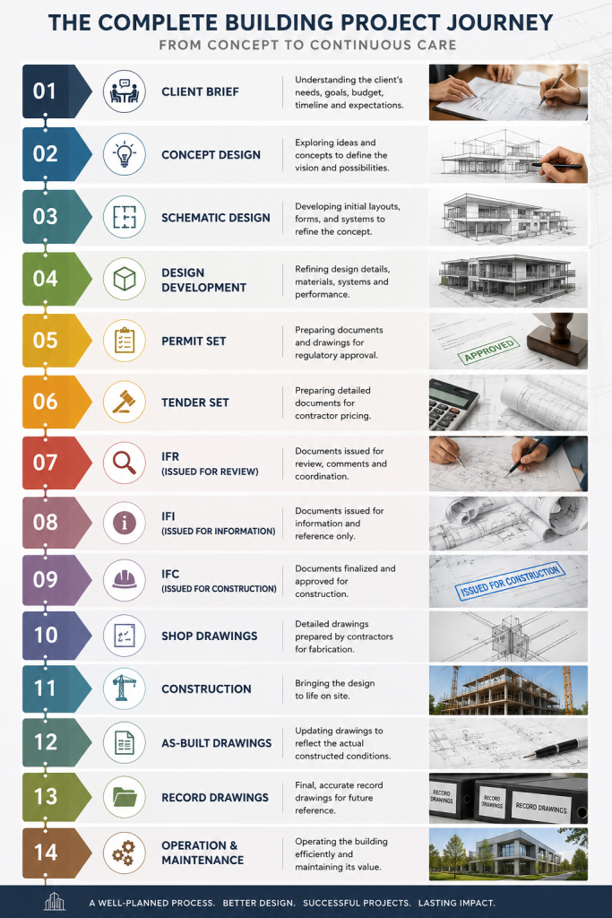
Client Brief → Concept Design → Schematic Design → Design Development → Permit Set → Tender Set → IFR (Issued for Review) → IFI (Issued for Information) → IFC (Issued for Construction) → Shop Drawings → Construction → As-Built Drawings → Record Drawings → Operation & Maintenance
Knowing where a drawing sits in this sequence tells you instantly how much to trust it. A concept drawing will change repeatedly. An IFC drawing is approved and final — it’s the only version that should ever be used on site.
Construction Drawing Sets: Permit, Working, and Construction Sets
| Set Type | Purpose | Who Uses It |
|---|---|---|
| Permit Set | Secure code approval from authorities | Architects, building officials |
| Working Set | Coordinate design and price the project | Architects, engineers, consultants |
| Construction (IFC) Set | Guide the actual build on site | Contractors, subcontractors |
Each set carries more detail than the last. A permit set proves code compliance; a construction set includes reinforcement, anchor points, and finish specs down to the last screw.
The 45+ Types of Construction Drawings, Fully Explained
This is the most detailed breakdown you’ll find on this topic — organized by discipline so you can find exactly what you need.
Architectural Drawings
| Type | What It Shows |
|---|---|
| Site Plan | Aerial view of the property, roads, boundaries, and topography |
| Floor Plan | Room layout, dimensions, walls, and fixtures per level |
| Elevation | External faces of the building, finishes, and window/door sizes |
| Cross Section | Vertical slice through the building showing hidden and visible elements |
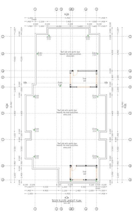
| Roof Plan | Roof shape, slope, drainage, and material layout |
| Reflected Ceiling Plan (RCP) | Ceiling layout, lighting, and finishes viewed from below |
| Landscape Drawing | Planting, hardscape, paths, and external features |
| Furniture Plan | Furniture layout and space planning |
| Finishing Drawing | Floor patterns, paint, plaster, and ceiling finishes |
| Demolition Plan | Elements to be removed in renovation projects |
| General Arrangement (GA) Drawing | Overview combining plans, elevations, and sections |
| Working Plan | Site-ready version used daily by the construction team |
| General Notes | Text-only sheet covering codes, abbreviations, and legends |
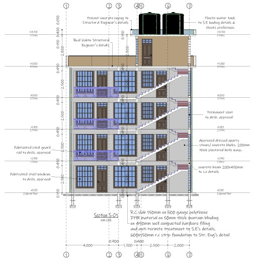
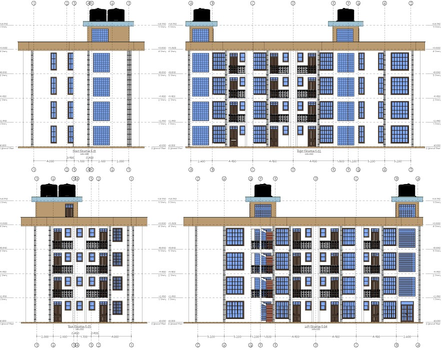
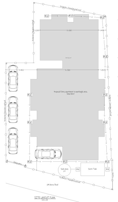
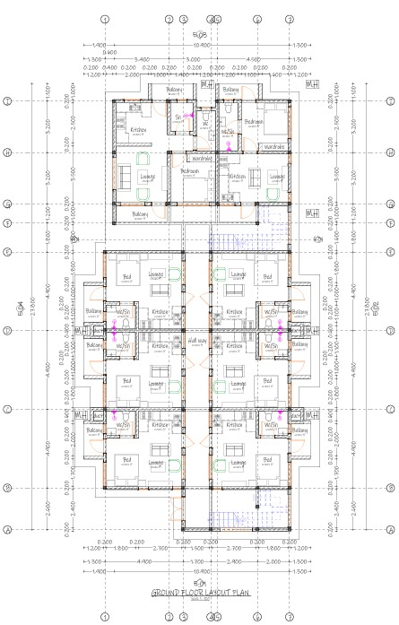
Read: Basic Room Dimensions: Standard Room Sizes for Every House (Complete 2026 Guide)
Structural / Engineering Drawings
| Type | What It Shows |
|---|---|
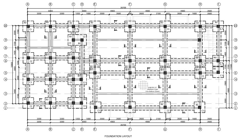
| Foundation Plan | Footing sizes, positions, and depths |
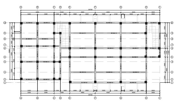
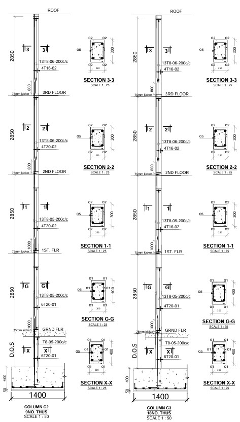
| Column Layout | Column sizes and grid positions, floor by floor |
| Plinth Beam Layout | Position and section of plinth beams |
| Lintel Beam Layout | Reinforced beams above doors and windows |
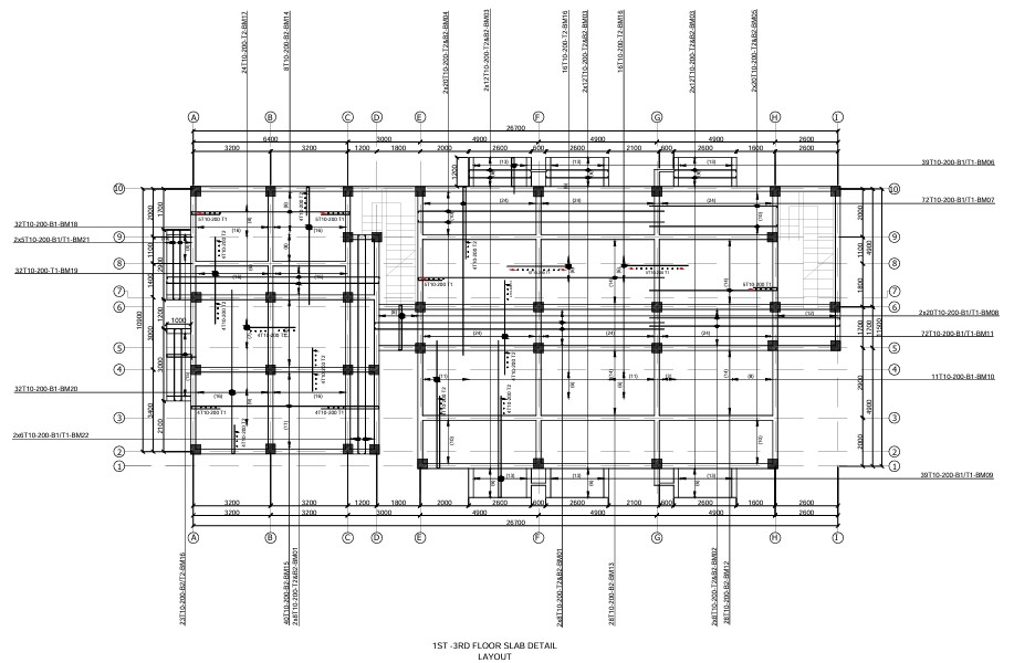
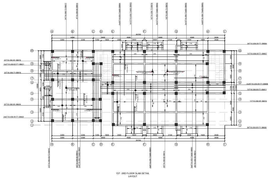
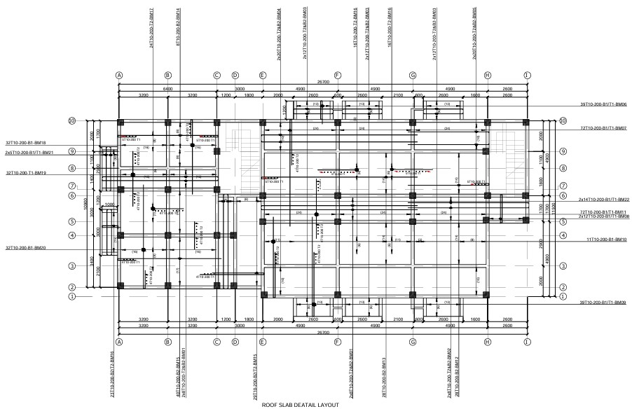
| Roof Beam & Shuttering Layout | Beam and formwork layout supporting the roof |
| Roof Slab Layout | Detailed slab, floor, and roof surface information |
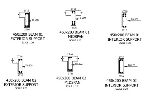
| Framing Plan | Beam, floor, and roof framework sizes and positions |
| Excavation Drawing | Depth, width, and method of site excavation |
| Block Plan | Wider-area view of the building relative to its surroundings |
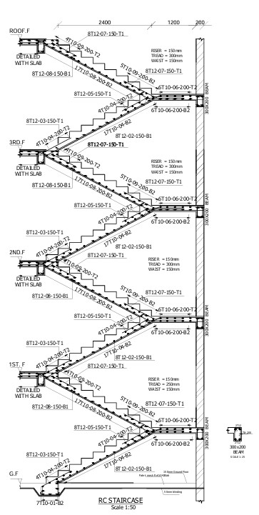
| Engineering Drawing | Guides fabrication or placement of engineered components |
| Assembly Drawing | How structural or fabricated components connect together |
| Component Drawing | Detail supplied by a manufacturer for a specific product |
Civil & Site Drawings
| Type | What It Shows |
|---|---|
| Site/Civil Plan | Grading, roads, utilities, and earthworks |
| External Works & Drainage Plan | Drainage systems and hard/soft landscaping outside the building |
| Environment Plan | Erosion control, sediment management, and vegetation clearance for sensitive sites |
| Location Plan / General Arrangement | Wider context showing the project’s relationship to its surroundings |
MEP & Specialist Drawings
| Type | What It Shows |
|---|---|
| Electrical Drawing | Wiring, outlets, panels, lighting, and load calculations |
| Plumbing Drawing | Water supply, drainage, and sanitary pipe routing |
| HVAC / Mechanical Drawing | Heating, ventilation, and air-conditioning layout |
| Firefighting Drawing | Fire hose points, sprinklers, and life-safety systems |
| Penetration Drawing | Exact size and location of openings through floors and walls for MEP runs |
| MEP Coordination Drawing | Color-coded overlay used to catch clashes before construction |
Fabrication & Site Execution Drawings
| Type | What It Shows |
|---|---|
| Shop Drawing | Fabrication detail prepared by a contractor or supplier |
| Installation Drawing | How equipment or systems are fitted on site |
| Detail Drawing | Enlarged view of a junction — windows, waterproofing, rebar laps |
| Production Drawing | Step-by-step instructions for workers and supervisors |
| Single Line Drawing | Simplified one-line depiction of a room or system layout |
| Working Drawing | Combines architectural, structural, and MEP data for daily site use |
Concept, Presentation & Record Drawings
| Type | What It Shows |
|---|---|
| Concept Drawing | Rough early sketch used to communicate an idea to stakeholders |
| Design Drawing | Refined proposal used as a benchmark before construction drawings begin |
| Perspective Drawing | Three-dimensional, realistic view of the finished building |
| Presentation Drawing | Polished drawing prepared for exhibitions, proposals, or publications |
| Submission Drawing | Prepared specifically to meet local authority by-laws for approval |
| Model | Physical or digital 3D representation used to identify design issues early |
| As-Built Drawing | Records the actual constructed conditions, including on-site changes |
| Record Drawing | Final, verified version of the as-built set, produced by the design team for handover |
| Scale Drawing | Any drawing reduced from real-world size according to a stated ratio |
| Technical Drawing | Umbrella term for any drawing made with a specific functional purpose |
As-Built vs. Record Drawings — What’s the Difference?
| Feature | As-Built Drawings | Record Drawings |
|---|---|---|
| Created by | Contractor, during construction | Design team, after reviewing contractor markups |
| Purpose | Track field changes as they happen | Provide final, approved project documentation |
| Accuracy | Reflects raw field conditions | Verified and cleaned up for official use |
| Timing | Ongoing or at project completion | At project closeout |
| Use case | Site coordination, inspections | Long-term facility management |
Schedules: The Drawings’ Companion Documents
Schedules are tables that list every instance of a specific building element and its full specification — they sit alongside the drawings rather than replacing them.
- Door schedules — number, size, material, ironmongery, and swing direction for every door
- Window schedules — quantity, size, manufacturer, glazing type, and finish
- Finishes schedules — floor, wall, and ceiling finishes per room
On larger projects, schedules prevent exactly the kind of coordination gap that causes delays — a window ordered to the wrong size, or a finish applied to the wrong room.
Construction Drawing Symbols, Scales, and Line Types
Common Symbol Categories
- Doors and windows (type, size, swing direction)
- Electrical (outlets, switches, panels, fixtures)
- Structural (grid lines, column marks, reinforcement callouts)
- Navigation (north arrows, section markers, elevation markers, material hatching)
Common Scales
| Scale | Typical Use |
|---|---|
| 1:10 – 1:20 | Detail drawings |
| 1:50 | Detail and interior drawings |
| 1:100 | Floor plans |
| 1:200 | Site plans |
| 1:500 – 1:1000 | Location and block plans |
Line Types
Solid lines represent visible edges, dashed lines represent hidden elements, and centerlines mark symmetry or alignment. Consistent line weight is what separates a clear drawing from a confusing one.
How to Read Construction Drawings — Step by Step
- Check the title block — project name, sheet number, scale, and revision date
- Use the drawing index — sheets are usually grouped by discipline (A = Architectural, S = Structural, M/E/P = Mechanical/Electrical/Plumbing)
- Confirm the scale and apply it with a scale ruler or digital tool
- Read the legend before interpreting any symbol
- Trace the grid lines to locate specific areas
- Follow callouts to their referenced detail or section drawing
- Cross-check disciplines — confirm architectural, structural, and MEP drawings agree
- Review schedules and specifications for information the plan itself won’t show
Reading drawings is a skill built through repetition — start with a simple residential floor plan and trace every dimension back to its source.
Common Construction Drawing Mistakes and How to Avoid Them
| Mistake | Consequence | Fix |
|---|---|---|
| Working from an outdated revision | Wrong work built on site | Strict version control and revision logs |
| Missing dimensions | Guesswork by the site team | Thorough review before drawings are issued |
| Scale misreading | Wrong quantities ordered | Always confirm the printed scale, never assume |
| Poor cross-discipline coordination | Clashes found mid-construction | BIM-based coordination reviews |
| Uncontrolled drawing distribution | Multiple conflicting sets in circulation | Issue by version, restrict access to approved sets |
BIM vs. CAD Drawings
CAD (Computer-Aided Design) produces flat 2D or 3D drawings as static files, drawn discipline by discipline. BIM (Building Information Modeling) builds a single, data-rich 3D model that automatically updates every linked drawing when a change is made — which is why BIM projects catch far more clashes before they ever reach the site.
Best Software for Construction Drawings
| Software | Best For |
|---|---|
| AutoCAD | 2D drafting and precise technical detailing |
| Revit | BIM authoring and multidisciplinary coordination |
| ArchiCAD | Architectural BIM modeling |
| Tekla Structures | Structural steel and concrete detailing |
| Civil 3D | Site, grading, and civil engineering drawings |
| Bluebeam Revu | PDF markup, redlining, and drawing review |
| Navisworks | Clash detection across combined models |
| SketchUp | Fast conceptual 3D modeling |
| Trimble Connect | Cloud-based multi-discipline coordination |
| Procore / PlanGrid | Cloud drawing and document management |
Construction Drawing Standards
Drawings follow recognized standards — ISO, ANSI, AIA guidelines, and local building codes — so a symbol, line type, or title block means the same thing to every professional who reads it, regardless of where they trained. Standardization is what lets an architect, contractor, and inspector who have never met work from an identical understanding of the same sheet.
Drawing Revision Control
Every change is tracked through revision numbers, revision clouds marking exactly what changed, and an issue log. The most common documentation failures on real projects come down to simple version control gaps:
| Problem | Why It Happens | Solution |
|---|---|---|
| Uncoordinated sheets | Disciplines not cross-checked before issue | Coordination reviews before every issue |
| Missing revisions | Changes made but not logged | Maintain a detailed, dated change log |
| Multiple versions in circulation | No central source of truth | Issue drawings by version, restrict access to approved sets |
| Limited field access | Site relying on printed, outdated sheets | Cloud-based access with offline capability |
| Excessive RFIs | Drawings unclear or contradictory | Clear callouts, legends, and linked details on every sheet |
RFIs, Submittals, and Drawing Coordination
An RFI (Request for Information) is a formal question a contractor raises when a drawing is unclear or contradictory. A submittal is documentation — often shop drawings or product data — sent to the designer for approval before fabrication or installation begins. Together they form the feedback loop that keeps drawings and site reality aligned:
Drawing issued → RFI raised → Response given → Drawing revised → Approved for construction
Common Questions
Frequently Asked Questions
They communicate design intent, dimensions, and materials so a project can be permitted, priced, and built accurately.
“Blueprint” refers to an outdated printing process; the correct modern term is construction or technical drawing.
IFC is approved for construction, IFR is issued for review or reference, and IFI is shared purely for information.
Licensed architects, structural engineers, and MEP consultants prepare the design drawings; contractors and suppliers prepare shop drawings and as-builts.
A cover sheet, general notes, legend, site plan, architectural, structural, and MEP drawings, schedules, details, and specifications.
As-builts are the contractor’s raw field markups; record drawings are the design team’s verified, final version of the same information.
Approved, signed drawing sets form part of the contractual documentation on a project and can be referenced in disputes.
AutoCAD and SketchUp are common starting points before moving into BIM platforms like Revit.
Building Information Modeling — a coordinated 3D model that generates and automatically updates every linked drawing.
They record the true final condition of a building, which is essential for maintenance, renovation, and facility management.
A hand-drawn or digital outline marking the specific area of a sheet that changed in the latest revision.
A permit set proves code compliance to authorities; a construction (IFC) set contains every detail needed to actually build.
Final Thoughts
Construction drawings are the shared language that keeps designers, engineers, and contractors working from the same page — literally. Understanding the full range of drawing types, how they progress through a project, and how to read them properly protects your budget, your timeline, and the quality of the finished building.
At VIVEROCK, our integrated architecture, structural engineering, and contracting teams produce and coordinate every drawing type covered in this guide on our own projects across Nairobi and beyond. If you’re planning a project and want documentation that’s clear, coordinated, and buildable from day one, get in touch with our team.